The structural analysis software RFEM 6 is the basis of a modular software system. The main program RFEM 6 is used to define structures, materials, and loads of planar and spatial structural systems consisting of plates, walls, shells, and members. The program also allows you to create combined structures as well as to model solid and contact elements.
RSTAB 9 is a powerful analysis and design software for 3D beam, frame, or truss structure calculations, reflecting the current state of the art and helping structural engineers meet requirements in modern civil engineering.
Do you often spend too long calculating cross-sections? Dlubal Software and the RSECTION stand-alone program facilitate your work by determining section properties of various cross-sections and performing a subsequent stress analysis.
Do you always know where the wind is blowing from? From the direction of innovation, of course! With RWIND 2, you have a program at your side that uses a digital wind tunnel for the numerical simulation of wind flows. The program simulates these flows around any building geometry and determines the wind loads on the surfaces.
Are you looking for an overview of snow load zones, wind zones, and seismic zones? Then you are in the right place. Use the Geo-Zone Tool to determine quickly and efficiently snow loads, wind speeds, and seismic data according to ASCE 7‑16 and other international standards.
Would you like to try out the capabilities of the Dlubal Software programs? You have the opportunity to do so! The free 90-day full version allows you to thoroughly test all our programs.
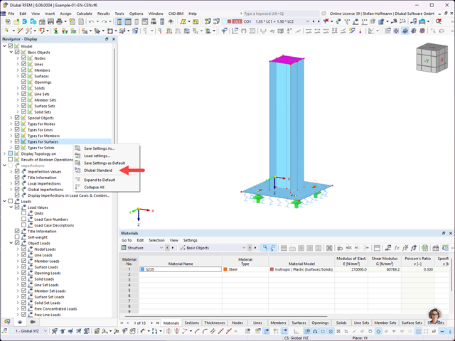
If you receive an RFEM 6 or RSTAB 9 file for further processing, the structures will be displayed in the program using the display settings of the last editor.
If this display does not meet your own requirements, you can simply right-click the free area of the Navigator – Display and select "Dlubal Standard". This returns the settings to the default values.
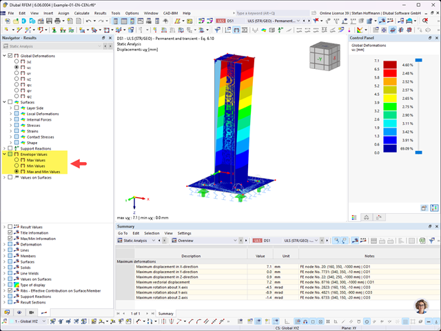
Please note that the enveloping results are usually shown when displaying the results of design situations or result combinations.
There are three options to graphically display the results of deformations, internal forces, and support forces: Max and Min-values can be displayed separately. To display both envelopes from the extreme values on the model, select Max and Min-values.
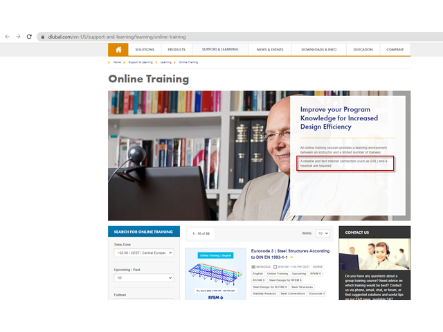
In the case of online training, communication between the speaker and the participant is live using the Internet. During the training, each participant can ask questions via chat at any time. You need a reliable, fast Internet connection and a headset. A dongle is no longer required, as the licensing of the new program generation (RFEM 6, RSTAB 9, RSECTION) is online.
If you want to simultaneously model on your computer during the training, you should use two monitors. This way, you can see your program interface and the video at the same time.
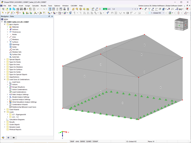
Yes, it is; as of RWIND 2.03, it is possible to automatically generate zones from the RFEM surface numbers.
Generate your RFEM model and start the calculation by running RWIND 2 not in the silent mode.
In RWIND 2, you can create zones from the RFEM surface numbers using Edit - Zones - Generate Zones from Surface Numbers.
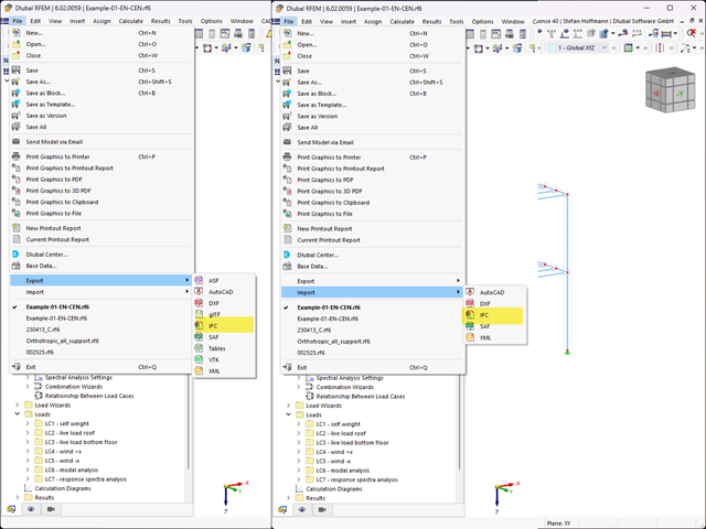
Use File - Export and File - Import to access the commands for exporting and importing an IFC file.
Version 4.0 is supported for both import and export. However, the older version 2x3 is only supported for import. Regardless of in which direction you exchange the data, you can process the StructuralAnalysisView as well as the ReferenceView (Coordination View).
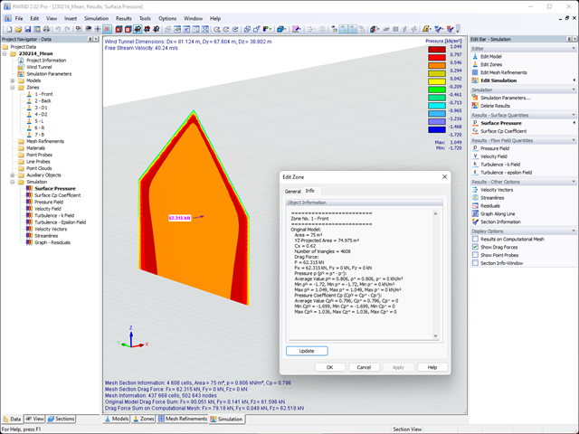
In RWIND, you can define zones and thus obtain a drag force for these zones. The information is available graphically and for each individual zone. This way you simply keep track of everything.
For complex structures, it can be helpful to quickly evaluate the results in a table.
You can evaluate the results in ParaView. For this, unzip the RWIND file and open the Sim001_V01_Surface.vtp file in ParaView in the RWIND_Simulations archive folder.
Since the zones are defined in the RWIND file, you can generate a .csv file, including the information of the cells.
This .csv file contains the information about the forces in the cells (front and back), related to the global axes. You can add up the forces of the zones with Excel and also create a vector. The data in ParaView are in SI units (for the forces [N]).
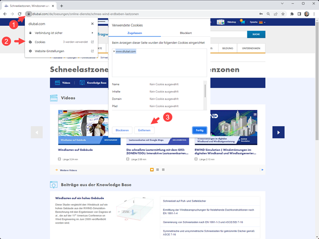
The page or the content of the Geo-Zone Tool is not loading? First of all, please check to see whether you are using outdated cookies, or not using all the necessary ones.
If so, you can quickly delete cookies in Chrome.
Then, you can agree to the cookies (allow the selection, or allow the cookie).
Our best experience has been with Google Chrome. Try it out. After that, the Geo-Zone Tool should work again without any problems.
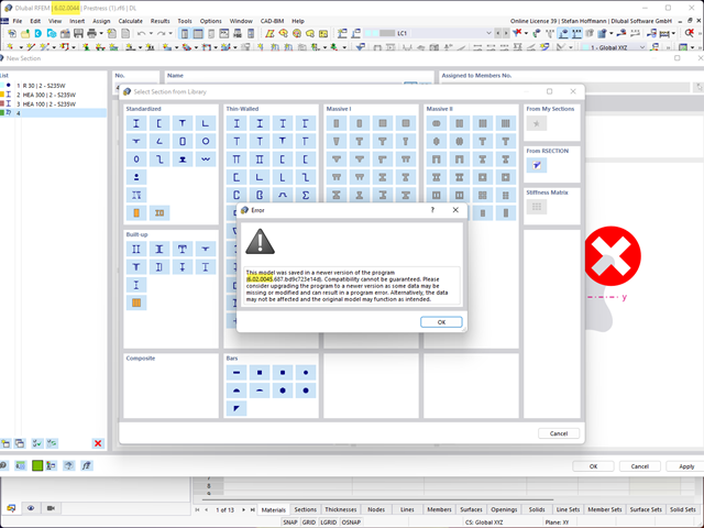
This error message is displayed if you are using a newer version of RSECTION 1 than RFEM 6.
Both versions should be on the same level in order to ensure the data compatibility of both programs, otherwise the new features of RSECTION 1 are not yet available in RFEM 6.
Make sure both versions are up to date.
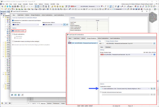
First, check whether you have activated the Combination Wizard and assigned it to a design situation.
Then, check the settings of the Combination Wizard. To get the automatically generated load combinations, you need to deactivate the "User-defined action combinations" option.
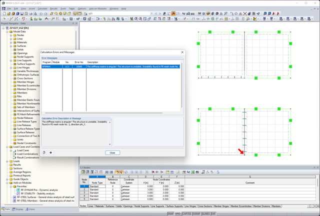
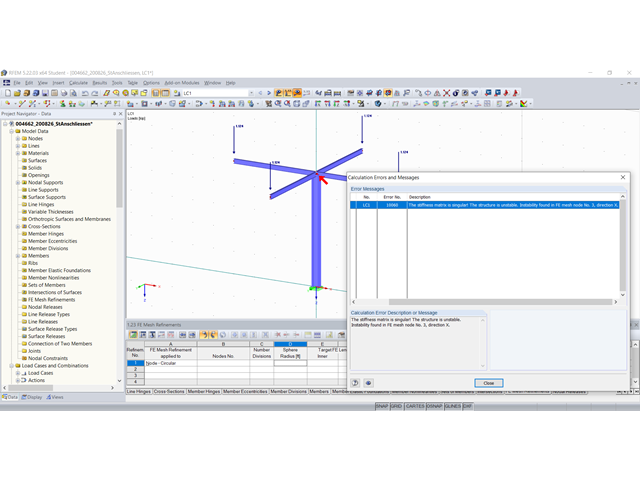
As of RFEM 5.27, there has been an adjustment in the solver that should better recognize hinge chains, which can make models unstable in the newer versions.
Adjustments in the solver regarding the consideration of line hinges - hinge chains (two surfaces each with a line hinge for the rotation about x on the same line) now lead to instabilities.
Please check your model accordingly.
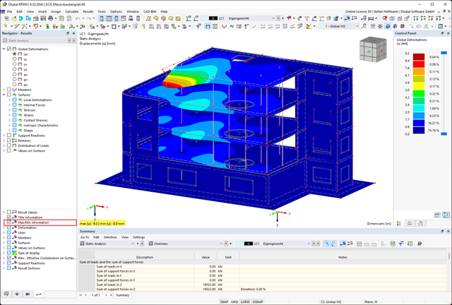
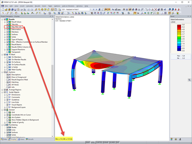
If the max/min information is no longer displayed, please check whether you have activated this in the Navigator - Results.
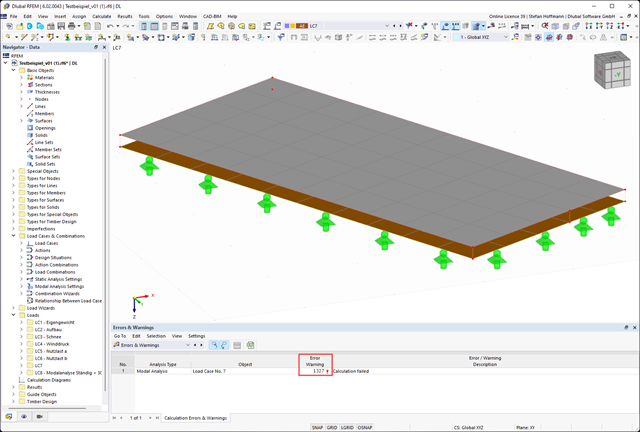
In many cases, Error 1327 describes inconsistencies that arise when transferring the data to the solver. You can proceed as follows:
Yes, it is.
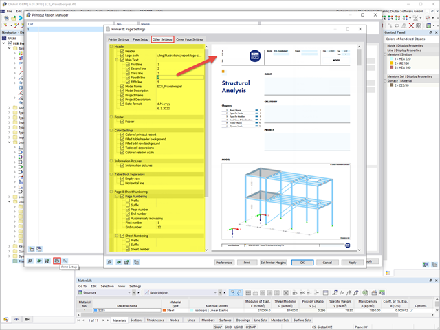
You can find various setting options in the Printer & Page Settings dialog box in the Other Settings tab. You can open this dialog box in the Printout Report Manager.
It is also possible to open this dialog box in the printout report.
Furthermore, it is possible to change the header directly in your account on our website. To do this, log onto your Dlubal account, go to the Company tab, and scroll down to the Printout Report entry. Here you can change the logo and the headers. After saving, the new header is transferred directly to your printout report.
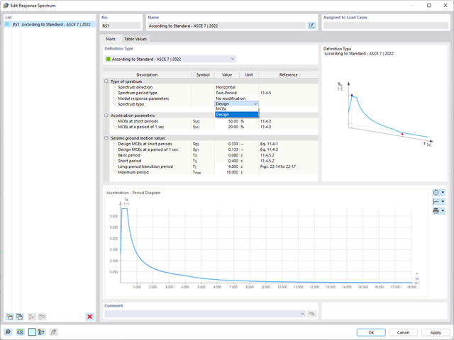
The ASCE 7-22 standard provides several types of design spectra. In this FAQ, we would like to focus on the following two design spectra:
The two-period spectrum is implemented in the program as usual. However, based on the data available from the standard, only the horizontal design spectrum / MCER spectrum as well as the modification related to the force and displacement can be offered.
For the multi-period design spectrum, discrete numerical values are specified. ASCE 7‑22 states that these values can be queried on the USGS Seismic Design Geodatabase page. In the current state of development, you have the option to create a user-defined response spectrum with a g‑factor (depending on the mass conversion constant) to use the data from the ASCE 7 Hazard Tool [1], for example.
Please proceed as follows:
No, the add-in is not installed automatically.
This means that the user must have Revit and RFEM 6 installed on the computer. However, Revit should be closed in this case.
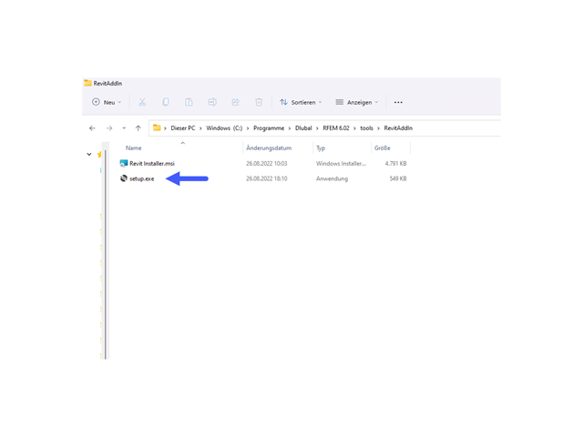
Afterwards, you have to navigate to the following folder:
This contains the "setup.exe" file. You can run it simply by double-clicking it. The Revit Add-in Installer will open.
After completion, the add-in is installed and the corresponding function is available.
It is also necessary to ensure that the server has been started in RFEM. You can also find this setting in the RFEM menu "Options" under "Program Options".
Currently, Revit 2021, 2022, 2023, and 2024 are supported.
Revit 2023 can be used as of the version 6.02.0049.Revit 2024 can be used as of the version 6.02.0068.
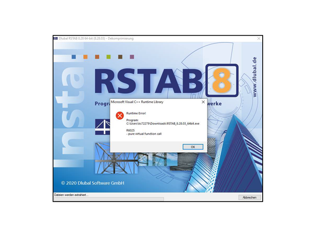
Error "R6025 - Pure virtual function call" is related to the MS Visual C++ libraries.
You can use this YouTube video for the error analysis:
It can also be useful to unzip the installation file and use the Dlubal RFEM 64-bit.msi file directly for the installation.
If the MAX/MIN information is no longer displayed, please check whether you have activated this in the Display navigator.
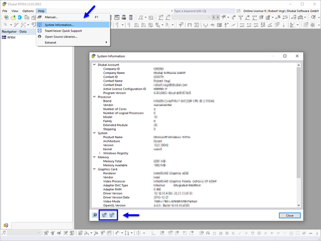
In RFEM, RSTAB, or RSECTION, open the Help menu and select the System Information option.
The program creates a diagnostic report, including the relevant system information. You can save this report by clicking the button or directly by email. As an alternative, you can save the system data in a file by clicking the button.
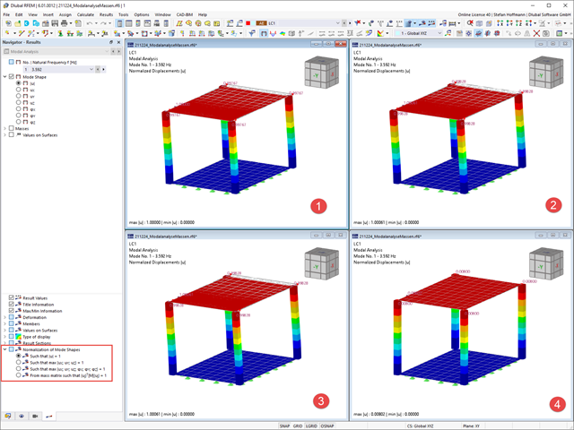
You can adjust the display of the mode shape normalization directly in the Results navigator. If the setting is changed, no recalculation is necessary.
Depending on the setting, the largest displacement or deformation represents the reference value 1, to which the other results are scaled.
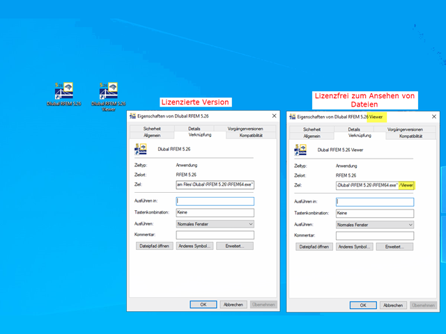
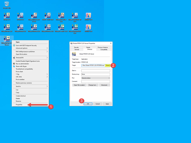
Please check whether you have started the licensed main program RFEM 5 / RSTAB 8 or opened the "viewer" by mistake. This viewer is only used to view files. It is license-free.
If you want to create files, you have to run the licensed main program. If the link does not exist anymore, you can copy the link to the viewer and then remove the "/viewer" addition in the properties.
To access the Viewer again, you only need to create a new shortcut on the desktop and enter the following parameters:
For RFEM 5.26:
"C:\Program Files\Dlubal\RFEM 5.26\RFEM64.exe" /Viewer
For RSTAB 8.26:
"C:\Program Files\Dlubal\RSTAB 8.26\RSTAB64.exe" /Viewer
The existing program link can also be copied and supplemented with the addition /Viewer.
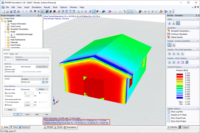
After a successful calculation, the checksums of drag forces are displayed on the original model and on the simplified model in RWIND Simulation in the legend of the graphic window. They are the resultants of the wind loading in the global directions X, Y, and Z.You can use it to compare the drag forces acting on the original model and the simplified model.The simplified mesh is a special mesh that envelops the original model, and thus defines the model boundary.
If there are significant differences between the checksums, you should increase the level of detail in the Edit Model dialog box for a more refined, simplified model.
However, if there are any differences, please note that any closed openings may also have an influence on the checksums.
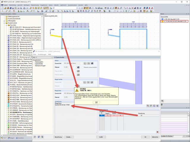
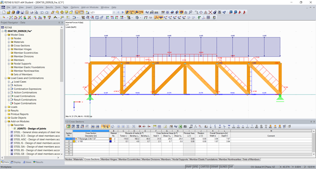
Check the cross-sections of your frame joint or connection.
The program checks whether the assignment of members is allowed for the calculation. If this is not the case, a footnote is displayed, which is explained in the "Comment" column. You have probably used a cross-section that is not intended for the connection design.
In our example, Note 23 is displayed and then the left beam is assigned manually: "Left Beam: Cross-section is not an I-section."
In Window 1.2 Cross-Sections, you can open the cross-section library to check which cross-sections can be selected for the frame joint type (activate the manual definition of geometry in Window 1.1 "General Data").
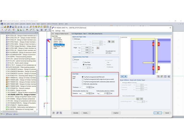
The RF‑/FRAME‑JOINT Pro add-on module designs rigid bolt connections between columns and horizontal beams, and classifies these connections. The rigid bolt connections are designed with the ultimate load method according to Eurocode 3 or DIN 18800.
The dimensions of an end plate can be defined in the add-on module. Bolts are possible in the extensions; however, only in the extension at the top.
A bolt row in the bottom extension is not intended, which is the reason the error message appears.
You can check the minimum dimension under the design hints in the add-on module.
The desired geometry can be entered in the RF‑/JOINTS Steel - Rigid add-on module.
Yes, this is possible with the RF‑/JOINTS Timber - Steel to Timber add-on module. You can design the connection of two diagonals if they are connected with steel plates and dowels, for example. For this, it is reasonable to use the "Main member only" joint type.
After selecting the node in the program, the connection is still marked as insufficiently defined due to the steel bottom flange.
You can now deactivate both steel members to perform the design for the connection of the two diagonals only.
This design is possible in the add-on module.
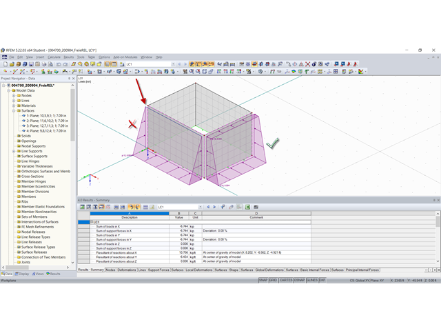
There are probably small inconsistencies in your modeling, causing the node coordinates to deviate from the coordinates of the free rectangular loads, and thus the loads are not displayed correctly.
Please check your model and correct it accordingly. The loads should then be displayed as expected.
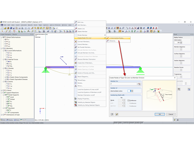
You can use the "Create Node 'on Line'" function available in the member shortcut menu to create a node that does not divide the member.
With this type of node, a line is not divided into two lines and remains complete. The nodal parameter δ describes the relative distance to the start node of the line. By creating nodes on lines, it is possible to apply nodal loads anywhere on the line or to force an FE node.
Then, you can apply a nodal load to this node at any angle as usual.
As you can check in the results, the force acts as expected.
If there is no common intersection point of the beam with the column, you can use the "Join Members" function in this case.
Thus, free members at a certain distance to a member can be joined to the nodes of this member.
In the "Settings" section, enter the number of the member whose nodes you want to join the free members to, or select it graphically. The text box below specifies the distance; that is, the circumference where RFEM looks for free member ends.
The "How to Connect Free Member Ends" dialog box section allows you to control how the free member ends are connected to the selected members: You can either move them to the nodes of the selected members or connect them with eccentric connections.
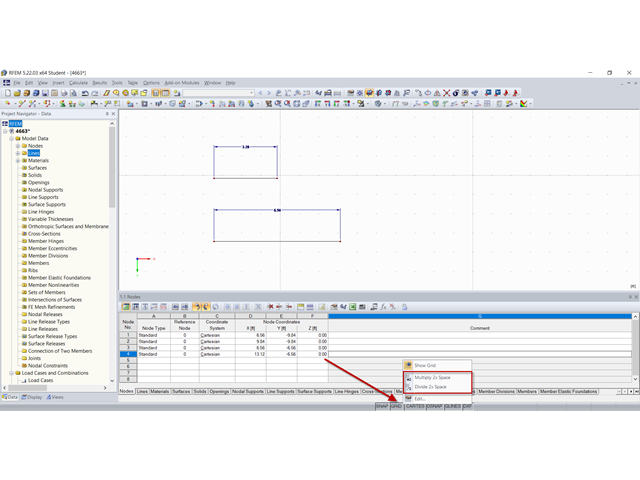
You can divide the grid spacing in the status bar by two (halve), or multiply it by two (double).
To do this, right-click the GRID button in the status bar and select the corresponding function in the shortcut menu.
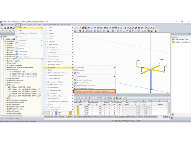
To do this, you can use the "Assign Member Properties Graphically" function, for example.
You can use this feature to graphically transfer the definition criteria of members for cross-sections, releases, and eccentricities to already created members.
After clicking [OK] to confirm the dialog box, the members are divided graphically at one-third division points. Now you can click the member sides to which you want to apply the selected properties (a release, for example). Click the center of a member to assign the release or eccentricity to both member ends.
A detailed description of this feature can also be found in the RFEM online manual.